
GIMBALLED ROCKET MOTORS
|
|
|
|
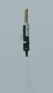
| The GYROC-2 gyro stabilised, finless, gimballed rocket in flight at UKRA 2006 in Lincolnshire, UK, June 2006. This flight of GYROC-2 used a G-class Aerotech 32mm diameter, long burn solid rocket motor. | ||
INTRODUCTION
Actively stabilised rockets represent probably the hardest technical challenge in amateur rocketry. The challenge in ensuring a rocket can maintain a particular trajectory by means of onboard control systems is extremely hard - hence the fact that not many people attempt it, or succeed.
In order to correct the trajectory of a rocket on its ascent, there are a number of methods that can be used for control. Some of these are:
- Control Surfaces
- Steering Vanes in the rocket exhaust for Thrust Vector Control (TVC)
- Gimballed motor(s) for Thrust Vector Control (TVC)
- Reaction Control Systems (RCS) e.g. Cold Gas Jets
As well as the control system, the rocket also needs a vertical active stabilisation system or guidance system that senses the position of the rocket and sends the appropriate signals to the control systems to correct any deviations in the rocket's trajectory. In order to guide the rocket, gyroscopes, accelerometers or combinations of the two can be utilised as the sensors.
Since the end of the 1990's, and the advent of piezelectric gyros for radio control helicopters, the use of gyros for this area of amateur rocketry has become more affordable. Initially, the drift of the piezo-gyros was considered to be a problem for amateur rockets, however, the latest piezo-gyros exhibit lower levels of drift.
Additionally, the availability of accelerometers such as the Analog devices ADXL series, has provided affordable accelerometers too. The mainstays were accelerometers such as the ADXL50. Now with the introduction of 2-axis accelerometers in single packages, there are even greater improvements.
Please note though, development of vertical actively stabilised rockets is hard. In terms of financial committment, constructing something that works, in developing the electronics, writing code, and doing mathematical calculations, all involve a high degree of focus if a vertical actively stabilised rocket is to work, Be prepared for having to do dozens or more tests to get something to work, and a large number of crashes - it's not cheap.
THE STATE OF THE ART
MARS has a larger than usual collection of hard core rocketry electronics gurus. The can-do/practical testing approach of MARS lends itself to those who want to fly cool electronics experiments. There are some cool electronics experiments in MARS though, that really do eclipse all others.
Probably the pinnacle of technical achievement in UK amateur rocketry is GYROC 1 - the gyro stabilised, gimballed rocket developed by rocketeers, and MARS members, James Macfarlane and Mike Procter.
The gyro stabilised, gimballed rocket has been under development since 1995, when I thrust an article from High Power Rocketry (HPR) Magazine in front of James Macfarlane and said "Why don't you build something like this ?". Little was I to know that he would, and not only that, but he would build a digital version.
The GYROC-1 gyro-stabilised, gimballed rocket, uses a scratch built 2-axis gyroscope, together with a scratch-built gimballed mount for standard 24mm diameter solid rocket motors. To the best of my knowledge, the GYROC project is the only one of its kind developed in the U.K. and probably one of the only ones in the World's amateur rocketry community. It has taken many years to develop, and the fact that such talented electronic engineers as James and Mike have taken so long to develop this system, would seem to indicate how serious an undertaking, a project such as this is.
The GYROC 1 rocket flew successfully over 10 times, including a few brief hovers, in addition to the controlled ascents, before it was replaced with GYROC 2. Between flights, a phenomenal amount of work went into tweaking the electronics and the software, and on each flight, the control and active stabilisation system generally got a bit better. It was the amount of time required between flights to work on the system that resulted in the more advanced GYROC 2 rocket - which requires little work between flights.
AIRFRAME
The airframe of GYROC 1 is constructed from 80mm diameter hand-laid fibreglass airframe tubing recovered from a rocket that blew up in 1995, called ADV. There are no fins, and no nosecone. The rocket does not go high enough or fast enough to really require a nosecone, and does not need fins because it is actively stabilised and controlled. A small phenolic airframe tube sits atop the main body of the vehicle, and holds the parachute recovery system.
For some flights, GYROC 1 has launched from a 3 foot length of Black Sky Rail, and for other launches, it has been fitted with 4 legs, and has taken off from just being sat on the ground on its legs. The on board timer system originally used pull pin initiation, and on the first launch using the legs rather than the rail, the importance of the positioning of the pull pin was demonstrated, when the pull pin was placed too far to one side, and the rocket tipped over after launch!
THE GYROSCOPE
The scratch built gyroscope for GYROC 1 comprises a central rotor wheel (from an old bicycle dynamo) with 8 hand wound magnetic poles around it. The rotor wheel sits on a graphite bearing (a 5mm diameter propelling pencil lead), with 4 Infra-Red reflectometers arranged as 2 differential pairs, reading a pattern fixed to the undersurface of the rotor wheel.
ROTOR SPIN-UP
A 5th Infra-Red reflectometer is mounted perpendicular to the 4 other Infra-Red reflectometers, and measures reflection from a striped pattern fixed around the edge of the rotor wheel - this is used for the rotor wheel spin up.
When a stripe passes the reflectometer, the reflected Infra-Red is picked up by the detection section of the 5th reflectometer, and a current is pulsed through a pair of the coils to create a magnetic field. This pulsed magnetic field interacts with the magnetic poles of the dynamo rotor, and causes it to spin up to 12,000 rpm.
THE GYROSCOPE CIRCUIT
At the heart of the circuit sits a Microchip PIC 16F84 microcontroller clocked at 4MHz. The circuit itself consists of a sampling Analogue to Digital Converter which passes its results through a software PID Controller. The software PID Controller then generates Pulse Width Modulated (PWM) output signals to drive 2 standard Futaba servos.
FLIGHT DATA RECORDER
There is also a separate scratch-built flight data recorder (using an EEPROM) driven by the PIC 16F84 Microcontroller, that plugs into the main control board, and allows the flight events to be analysed after the flight. The flight data recorder is built onto the back of a 9-way D-plug. For flight data recording, this is plugged in to a 9-way D-socket on the main circuit board. To read the data from the flight data recorder, the flight data recorder is plugged into a scratch built reader connected to a laptop PC.
SPIN-UP CIRCUIT
There is a separate circuit for spin-up of the gyroscope rotor wheel.
TIMER CIRCUIT
Until such time as the vehicle can be taught to hover nicely and then land, there is a parachute recovery system which is triggered by a 555 timer circuit onboard. Originally, the timer circuit was triggered by a pull pin, but it has now been modified to use a sensitive g-switch triggering system.
POWER CIRCUIT
There is a separate circuit for a switch mode power supply, which is used to supply all the separate voltages for diverse circuits in the system. This is powered from a rechargeable 4.8 Volt Ni-Cad battery pack, previously used for radio control aircraft.
THE CONTROL SYSTEM
The control system comprises of 2 standard Futaba servos with their inputs connected to outputs from the PIC 16F84 flight computer. The servo horns connect to flexible push rods which are connected to a universal joint mounted at the bottom of the airframe. One end of the universal joint is attached to the airframe, and the other end is fitted with an aluminium motor mount fabricated to accomodate short motors from 24mm diameter to 32mm diameter.
The thrust loadings are thus transferred through the motor mount and the universal joint to the airframe rear bulkplate.
SOFTWARE
The operating code onboard the gyro stabilised rocket, which controls just about everything the rocket does, was developed in PIC 16F84 assembly language by Mike Procter.
All the code and utilities were developed under the Linux operating system (running with Linux kernel 2.2). The code has not yet been released, but if it ever is, I shall place it on this website.
FLIGHT TESTING
GYROC 1 - Flight 1 (August 1995 I think)
 |  |
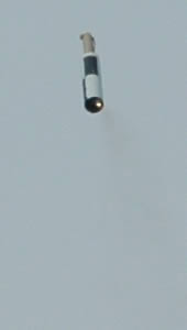
| The use of a low thrust motor meant that the rocket near enough launched and then hovered above the launch pad on its thrust! | As the motor thrust decreased, the rocket slowly descended, all the while gimballing the motor to try and stay vertical. |
The first launch of GYROC 1 was conducted at the International Rocket Weekend (IRW) at Largs in Scotland. Because of its experimental nature, the watching crowd of rocketeers were kept well back. The first launch was a brief hop compared with later flights, but provided the confidence that the concept could be made to work. It would be fair to say, that the hovering was accidental, due to the motor thrust being low, however, the effect on the crowd watching the launch was quite dramatic - cheers broke out (people thought it was supposed to hover!). The flight at least showed, that for future flights, hovering under motor thrust could be achieved.
GYROC 1 - (September 2001)
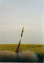 | 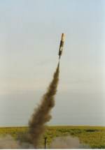 |  |
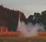
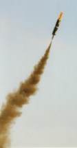
| The finless, noseless, gyro stabilised, gimballed rocket launches | The gyro stabilisation system has detected the rocket's position and is gimballing the motor to correct its trajectory. | Fine adjustments are made to the rocket's trajectory to maintain its trajectory as precisely as possible. |
 | 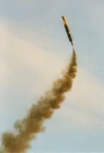 | 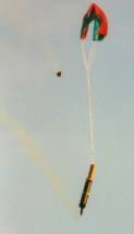 |
| Towards the end of a motor burn, the rocket tends to lose some stability and the gyro stabilisation system has to compensate. | A bit of over-damping? There are still some tweaks needed to the system. | After motor burn-out, the rocket reaches apogee and a scratch-built timer deploys a parachute to safely recover the rocket. |
This launch of GYROC 1 took place in Cambridgeshire in 2001, and as can be seen from the exhaust, GYROC 1 was powered on an Aerotech Blackjack motor for the launch. By this point, GYROC 1 had acquired a small, somewhat unaerodynamic recovery bay atop the main airframe, and a home made parachute built by Catherine Procter.
CONCLUSIONS FOR GYROC 1
The launches of GYROC 1 since its inception in 1995, have become increasingly more controlled. Almost all the improvements to the design have involved tweaking the PIC 16F84 software, especially the damping. Early launches tended to see over damping, then there was a period of under damping, now the damping seems to have been conquered somewhat.
The mechanical control system and main airframe has not needed modification. An additional parachute bay was added after several flights, and on some launches, landing legs were fitted, but essentially, the vehicle has remained structurally the same.
GYROC 2
Over the past 3-4 years, work has moved on to the GYROC 2 flight test programme, the successor to GYROC 1. GYROC 2 still uses a gimballed motor control system, but the home made gyro has been replaced with 2 commercial solid state rate gyros, the PIC 16F84 Microcontroller has been upgraded to a PIC 16877, the software has been upgraded, and the motor mount for GYROC 2 can be fitted with motors up to the diameter of the Aerotech 32mm solid motor size.
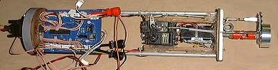
The Gyroc 2 internals. To the right are the gimbal control servos and the gimballed mount. To the left is the flight computer. Not visible are the gyros which are mounted on the reverse side of the flight computer.
The new solid state rate gyros used for GYROC 2 are somewhat more expensive than the homemade gyro used on GYROC 1, and also considerably more expensive than those used in radio control helicopters and aircraft. The results from the launches indicate they are worth it however. The whole system is now lighter and smaller, since the spin up circuit is no longer needed, nor are the detection circuits, so the whole electronics system can be incorporated onto one PCB.
GYROC 2 has now flown more than 10 times, with the first flight taking place in February 2002. GYROC 2 has validated the new systems with a vengeance. All flights have been perfectly vertical, have demonstrated an ability to maintain vertical attitude during hover, and have demonstrated an ability to try and stay vertical even during thrust tail-off. On 2 of the flights, GYROC 2 demonstrated horizontal translation - on the 3rd flight, it launched to around 30 feet, hovered, and then translated sidewards around 40-50 feet before deploying a parachute to descend. It repeated this feat on a number of following flights as well.
The improved design of GYROC 2, means the stability is far better, so there is no need to re-jig the software calibration values between every flight or two. It is literally, sufficiently successful now to be a plug and play vehicle so to speak.
GYROC 3
Whilst work will continue with GYROC 2 now it is demonstrating such good results, construction started in 2004, on a far more capable version, known not surprisingly, as GYROC 3. GYROC 3 will be capable of actively stabilised vertical flights to far higher altitudes than either GYROC 1 or GYROC 2, and with a much longer motor burn, and more control for translation during flight. Demonstrating the complexity of working with vertical active stabilisation systems, progress with GYROC 3 has taken longer than anticipated, and as of 2006, it is yet to launch, but this is largely because it is a larger, much more capable and much more advanced flight test vehicle.
THE NOT SO STATE OF THE ART
Watching the ever more impressive flights of James and Mike's gimballed, gyro rocket, was the inspiration required to kick start myself into having a crack at an active stabilisation rocket. The design I am working on is to initially fit in a 2.6 inch diameter airframe, and then hopefully, fit in a 2 inch diameter (54mm) airframe if successful. Essentially, to make it as small and light as possible.
The factor that controls how small it is, is basically the size of the control equipment required to provide enough power to gimbal the motor. To this end, I am using micro-servos, with a commercial system which is essentially, a modified sun seeker system (modified for use as a horizon sensing system) to keep the rocket vertical. Eventually, I will probably move to using radio control helicopter rate gyros, but at the moment, just want to get the basic control system working on short duration, low altitude tests first. The micro-servos are only powerful enough to use for gimballing small motors, so the small size of the vehicle helps here. They are suitable however, for use with larger motors if used for aerodynamic control system operation, or for thust vanes or even cold gas jets.
The advantage of this system is it does not require any software to be developed for it. The disadvantage is a much less flexible system than the GYROC rockets.
I will place some details online when I get chance (probably in a decade or so, knowing me).
NOTES
The information above clearly lacks close up photos, plans and circuit diagrams of the GYROC rockets. The photo aspect will be remedied when I next get to play with the GYROC rockets, plans and circuit diagrams may take bit longer!
I get quite a bit of email, so I will warn people in advance of the following:
1. Unfortunately, no, I don't have access to the source code of the GYROC rockets, so there's no point in asking me for it. If I had it, it would be on this website. If it's not here, it's because I don't have it!
2. No, I don't have the circuit diagrams for GYROC, much though I would like to. Again, if I had them, I would put them here on my website.
If you want to build one, your best bet would be to read all the sources I have tried to assemble below to help people. I know this is going to sound harsh, but just emailing me and asking me how to build one is not clever. Guidance is the type of subject that requires a lot of thought, if you're not prepared to put the work in and try and learn first, or if you want someone to do it all for you, maybe you should consider another project. Rocketry guidance is hard, it's as simple as that. If you building or trying to build, or sourcing the parts to build something similar, then feel free to email and ask specific questions, and I'm more likely to be able to help, but just asking me how to build a guidance system, is like asking "how long is a piece of string", and saying you're thinking about building a guidance system is great, but I really don't have time to help, that is why I put the information here instead. I really do get deluged with my business email as it is.
ONLINE LINKS
The following links are a very good place to start for those interested in guidance:
- The r.m.r. Guidance FAQ
- PSAS Amateur Inertial Navigation Systems
- Cristiano Casonati's excellent European active stabilisation systems (in Italian, but very detailed!)
See Also
Hybrid Rocket Science, Hybrid Rocket Help Clinic, Amateur Hybrid Motors, Amateur Liquid Rockets, Guidance, Gimballed Motors, Launch Controller, UK Rocketry Vendors, UK Rocket Groups, UK Space Organisations
