
HOME NETWORKING
The plan was, to run shielded (STP) CAT 5e cabling to each room, with between 4 to 20 networking ports per room. Although this may sound excessive, it is surprising how rapidly ports get used in practice. The network ports are fitted into a double socket, with 4 network ports per socket (2 for phone, and 2 for data).
Ethernet Patch Panels and Switches
This has neccessitated the use of 2 x 48-way CAT 5e patch panels, and a 16-way CAT 5e patch panel to wire the 2 phone lines into. The computers are patched in to a Netgear 24-port Ethernet 10/100 baseT switch. Even with that amount of network plumbing, I've run out of patch panel points, and need more!
A 24-port switch may seem a bit over the top, however, by the time PCs in different rooms, print servers and laptops have been taking into consideration, it is easy to reach double figures in terms of port usage, and then clearly, there will be a need to allow for future capacity. This would tend to favour 16-port and 24-port switches or hubs, rather than those with less ports. I chose a 24-port switch mainly because I already have several computers operating as servers, and also use laptops in various rooms. I could easily see ports being used up, and thought I'd better allow sufficient headroom for future capacity.
CAT 5 cabling for ethernet networking
Shielded CAT 5e cable was used because with the possibility of numerous different wireless devices becoming prevalent in the future (Bluetooth, 802.11, wireless alarm systems, wireless security cameras, and DECT phones), I didn't fancy RF interference. Shielded cable significantly reduces this possibility whilst ensuring the network integrity remains pretty robust. Many moons ago, I worked for a company on microwave absorption, some of which was at S-band frequency (the same waveband as Bluetooth, 802.11, video senders and, I believe, DECT phones), and what I learned whilst involved in that research, coupled with my Physics Degree, and the subsequent telemetry work I have done returning data and video from onboard rockets, has given me an insight into interference at first hand, hence my desire to minimise its effects. That is not to say that unshielded cable is not suitable in the majority of cases, it is, and not only that, the Skin Effect in Electromagnetic Theory Physics shows that the chance of most domestic RF system signals affecting a buried unshielded cable is pretty small. It's just I suppose from first hand experience, I don't trust labels showing power outputs on domestic RF equipment to always be accurate!
CAT 5e cable was used over CAT 5 since it is tested and certified to higher bandwidths. Whilst not as high as the proposed CAT 6 and CAT 7 standards, the improvement of CAT 5e over CAT 5 seemed to be just about enough to justify using CAT 5e from a future proofing point of view. If it would extend the life of the LAN in terms of bandwidth, then I thought it would be worthwhile.
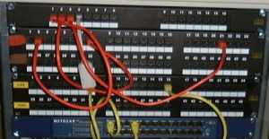
Figure 1: Patch panel and Ethernet switch
The photo shows the patch panel and ethernet switch arrangement in the rack. The red patch leads are patched from the 16-way phone patch panel at the top of the picture, into individual network ports on the patch panel section denoted by a piece of red insulation tape. The yellow patch leads are patched from the patch panel into the Ethernet switch.
The network topology is a standard star network, with separate sections of the patch panel designated for use for specific applications,e.g;
Local Area Network
- The LAN is used for connecting rack mounted, desktop and laptop PCs around the house.
Home Area Network
- The HAN provides future expansion capability to support internet enabled appliances and embedded systems, or for feeding video/audio signals around the house.
Phone 1
- Currently configured to support telephone line 1.
Phone 2
- Currently configured to support telephone line 2.
Each socket in each room is a double width socket, accomodating 4 CAT 5e modules, one for each of the applications above.
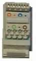
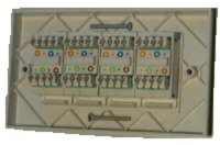
Figure 1: Patch panel and Ethernet switch
The images show a single CAT 5e module and 4 CAT 5e modules fitted in a double width wall socket. The CAT 5e modules are snap fitted into the double socket. The CAT 5e cable is fitted into the CAT 5e module by means of a Krone punch-down tool. As can be seen, the modules are colour coded so that the appropriately coloured CAT 5e cable can be fitted straight into the appropriate receptacle on the module.
Clearly, where demand in a particular room favours a specific application, the modules can be patched in to cater for that application, so instead of 1 of each application, 3 Local Area Network and 1 phone socket could be patched in.
The sources of the equipment were as follows:
| Patch Panels | Lets Automate |
| CAT 5 wall modules | Maplin Electronics |
| CAT 5 STP cable | Nova Electronics |
| Netgear 24-port 10/100baseT Ethernet Switch | Misco |
| Patch Leads | Farnell |
Network Construction
Wiring in the network was a time consuming and tedious task - especially when you're terminating 100 odd CAT 5e patch panel sockets and 100 odd CAT 5e wall sockets on your own. The CAT 5e wires were terminated into the patch panels and wall sockets using a Krone punch down tool, which made the task considerably more tolerable than soldering the wires on. All wiring was connected using straight through wiring.
Networking wiring convention
The wiring convention printed on the back of the patch panels seemed a bit confusing to the uninitiated, with 2 wiring conventions displayed (labelled A and B), with no details as to the difference. It took a multimeter and a short length of patch cable with bare wires at one end to work out which wiring convention was needed for a direct straight through connection (convention B). The A and B actually refer to 2 standards called 586A and 586B. It seems to be the convention to wire up according to the 586B standard from what I have seen. The network cable with bare wires at one end was plugged into a patch panel, and a multimeter was attached across each of the bare wires in turn, and at the other end, to the connectors in the patch panel. The multimeter was set to continuity testing, and by noting down which combinations produced beeps on the multimeter, the wiring convention was worked out.
EIA/TIA 568B Wiring Scheme
 |
| |||||||||||||||||||||||||||


Cable identification
Each cable was labelled at the Patch Panel using a Dymo Letra Tag label printer. This proved to be invaluable, especially when tracing any little inconsistencies in the wiring initially. Without having labelled the wires as they went into the patch panel, identifying which wire went where would have taken many, many times longer.
I also managed to lose a pile of screws to attach some of the 19" rack mounted equipment into the 19" rack. For the benefit of those who might have done similar, or may need additional fixtures, M6 nuts and bolts seem to work very well for fixing 19" equipment into a 19" rack.
